CT Current Transformers connection:
The connection of CTs in a single-phase system is very simple, but for a three-phase system there are 3 CTs that can be connected in two ways:
Star (Wye) connection:
In the star connection method, one terminal of the current transformer is connected to relays and other equipment, and the non-terminal is short-circuited to the ground. A neutral side may or may not exist in a three-phase system.
Delta Connection:
For a delta connection, the CTs are connected to each other in a delta fashion but pay attention to the polarity of the CTs when making the connection.
If the CTs are connected in a star on the transformer side, the CTs are usually connected in a delta and vice versa.
The polarity of CT:
Like any other transformer, CTs have polarity. Polarity refers to the instantaneous direction of the primary current relative to the secondary current and is determined by the way the transformer leads exit the enclosure.
All current transformers are depolarized. CT polarity is sometimes indicated by an arrow, and these CTs should be mounted so that the arrow points in the direction of the current flow. It is important to note the correct polarity when installing and connecting current transformers to power metering and protective relays.
CT ground:
The grounding of the current transformers is very important for the safe and correct operation of the protective relay.
According to the grounding standard of the current transformer, the secondary circuit of the current transformer should be grounded only in one place. This is independent of the number of current transformer secondary windings connected to the circuit.
CT burden:
A current transformer load is defined as the load connected to its secondary. Generally expressed in VA (volt-ampere).
In short, the connecting wires and connected meters form the load for the current transformer. In technical terms, this is called the load in the VA. This load affects the accuracy of the current transformer. In the design of the current transformer, the internal loss and external load of the current transformer are considered.
The load is expressed in VA by multiplying the secondary current by the voltage drop across the CT load (load). Current transformers are divided into categories based on accuracy, which in turn depends on the load of the CT.
What Does The Connection, Polarity And Loading Of The Ct Current Transformer Look Like?
Recommended Products
-
 View More >>
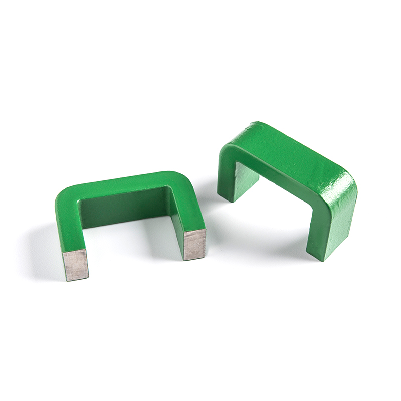
Non-Toroidal C-Type Cut Amorphous Nanocrystalline Cores
Industry: Amorphous Nanocrystalline Core
-
 View More >>
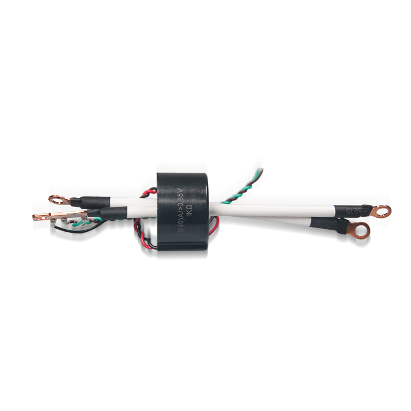
EHC-VCT Series for Power supply
Industry: Current Transformer
-
 View More >>
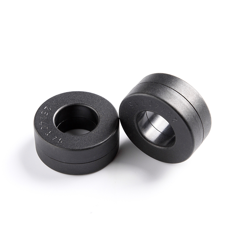
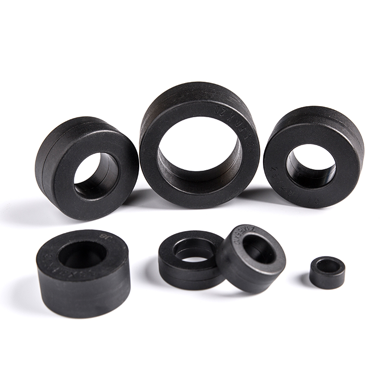
Transformers Cores Amorphous Nanocrystalline Cores
Industry: Amorphous Nanocrystalline Core
-
 View More >>
Amorphous Nanocrystalline Inductor Cores
Industry: Amorphous Nanocrystalline Core
-
 View More >>
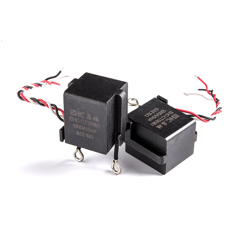
CTS Series Terminal High Precision Amorphous Nanocrystalline Current Transformers
Industry: Current Transformer
-
 View More >>
Rectangular hysteresis loop Cores
Industry: Amorphous Nanocrystalline Core
-
 View More >>
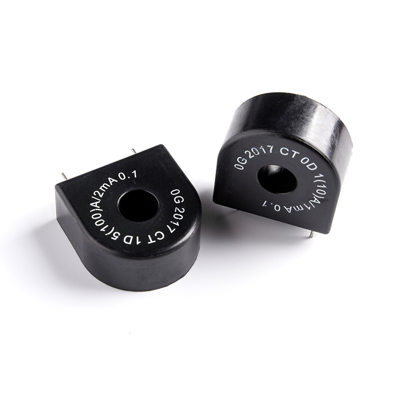
High Linear Current Transformers
Industry: Current Transformer
-
 View More >>
Common Mode Choke Amorphous Nanocrystalline Inductors
Industry: Amorphous Nanocrystalline Inductors

 English
 中文简体
中文简体 Deutsch
 日本語
日本語