1. Core Function and Purpose
Current Transformer (CT):
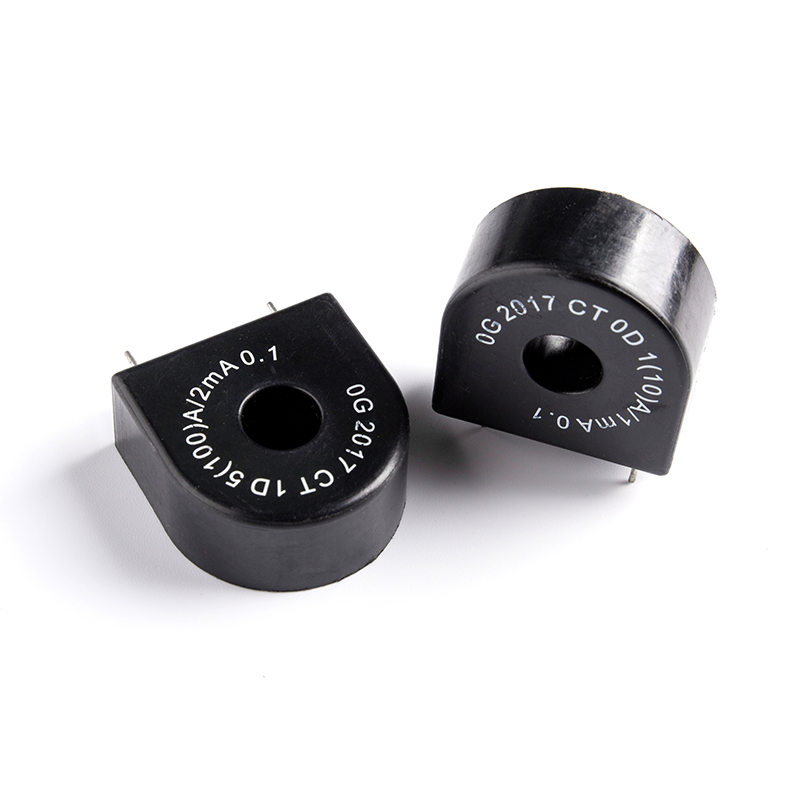
Core Function: To step down large currents in high-voltage or high-current circuits proportionally to standard low currents (typically 1A or 5A).
Purpose:
Safety Isolation: To isolate high-voltage, high-current circuits from measuring instruments, protective relays, and control devices, ensuring personnel and equipment safety.
Standardized Measurement: Allows the use of standardized, low-current rated meters and relays, reducing costs and increasing versatility.
Expanded Measurement Range: Enables ordinary ammeters to measure currents of thousands of amperes.
Operating Principle: Based on the principle of electromagnetic induction. The primary current generates magnetic flux in the iron core, which in turn induces a corresponding electromotive force and current in the secondary winding. It essentially acts as a "current source," meaning that regardless of changes in the secondary load (within the rated range), the primary current determines the magnitude of the secondary current.
Potential Transformer (PT - Potential Transformer / VT - Voltage Transformer):
Core Function: To step down high voltages in high-voltage circuits proportionally to standard low voltages (typically 100V or 110V).
Purpose:
Safety Isolation: To isolate high-voltage circuits from measuring instruments, protective relays, and control devices, ensuring personnel and equipment safety.
Standardized Measurement: Allows the use of standardized, low-voltage rated meters and relays.
Expanded Measurement Range: Enables ordinary voltmeters to measure voltages of tens of thousands of volts.
Operating Principle: Also based on the principle of electromagnetic induction, similar to a regular step-down transformer. It essentially acts as a "voltage source," meaning that regardless of changes in the secondary load (within the rated range), the primary voltage determines the magnitude of the secondary voltage.
2. Connection in the Circuit
CT:
Series Connection: The primary winding of the CT must be connected in series with the main circuit whose current is to be measured. This means that all of the main circuit current flows through the CT's primary. Imagine if we want to measure the current in a cable, we would need to pass this cable through the center of the CT (for a window-type CT) or connect the cable in series with the two ends of the CT's primary winding.
Reason: Only by doing so can the CT "sense" the true current changes in the main circuit and reflect them proportionally to the secondary.
PT:
Parallel Connection: The primary winding of the PT must be connected in parallel (across) the two points where the voltage is to be measured. Just like a regular voltmeter, it needs to be connected between the measurement point and a reference point (usually ground or another phase line).
Reason: The PT needs to "sense" the potential difference (voltage) between two points in the main circuit to transform it proportionally.
3. Primary and Secondary Winding Turns Ratio
CT:
Few Primary Turns, Many Secondary Turns: CTs are typically designed with very few turns in the primary (sometimes even just one turn, where the conductor passes directly through the core's opening), and a large number of turns in the secondary.
Current Ratio: . For example, a 400/5A CT means that when the primary current is 400A, the secondary current is 5A. Its turns ratio is .
Voltage Characteristics: When a CT is in operation, the primary current determines the secondary current. If the secondary is open-circuited, the entire primary current will be used for excitation, leading to high saturation of the core and the generation of extremely high voltages in the secondary. Therefore, the secondary side of a CT must never be open-circuited.
PT:
Many Primary Turns, Few Secondary Turns: The primary winding of a PT typically has a large number of turns, while the secondary winding has a small number of turns.
Voltage Ratio: . For example, an 11kV/110V PT means that when the primary voltage is 11kV, the secondary voltage is 110V. Its turns ratio is .
Current Characteristics: The secondary voltage of a PT depends on the primary voltage. If the secondary is short-circuited, it will lead to excessively large primary current, potentially damaging the PT or causing a fault on the primary system. Therefore, the secondary side of a PT must never be short-circuited.
4. Core Design and Magnetic Flux Density
CT:
Design Philosophy: To ensure measurement accuracy over a wide current range, the CT core is usually designed to operate near its saturation point or in a highly linear region. When the primary current changes, the magnetic flux also changes significantly.
Application Impact: Especially for CTs used for protection, they are required not to saturate under large fault currents to ensure reliable operation of relays. Therefore, the cores of protection-grade CTs are usually larger than those of metering-grade CTs.
PT:
Design Philosophy: To ensure the accuracy of voltage measurement, the PT core is typically designed to operate in the linear region of the magnetization curve, and at low magnetic flux densities, to minimize exciting current and measurement errors.
Application Impact: PTs are primarily used for voltage measurement and voltage relays, requiring high linearity, and core saturation is undesirable.
5. Secondary Side Safe Operation and Precautions
This is the most critical safety difference between CTs and PTs:
CT - Secondary "Must Never Be Open-Circuited":
Reason: If the CT secondary is open-circuited, the primary current (determined by the main circuit) will entirely become exciting current, causing the core to be highly saturated. According to Faraday's law of electromagnetic induction, , the secondary winding has many turns, and the rate of change of magnetic flux is extremely high, which will generate dangerously high overvoltages (several kilovolts or even tens of kilovolts) across the secondary terminals.
Consequences: This high voltage can break down the CT's secondary insulation, leading to equipment damage and posing a serious electric shock hazard to personnel.
Operating Requirement: When a CT is in operation, its secondary must always be kept closed, either short-circuited or connected to a low-impedance load (such as an ammeter or relay coil). When replacing instruments or performing maintenance, the CT secondary must be short-circuited before any work is done.
PT - Secondary "Must Never Be Short-Circuited":
Reason: A PT is essentially a step-down transformer. If its secondary is short-circuited, it will cause a sharp increase in secondary current, which in turn leads to excessive current in the primary, essentially short-circuiting the high-voltage line.
Consequences: The excessively large current can burn out the PT itself and may cause upstream circuit breakers to trip, or even lead to a power system fault.
Operating Requirement: The secondary side of a PT is typically protected by fuses or circuit breakers. During operation, short-circuiting the secondary should be avoided.
6. Burden (Load) Impact
CT:
Load Characteristics: The load (or "burden") of a CT refers to the sum of the apparent power (in VA) of all instruments connected to its secondary circuit. The rated burden of a CT indicates the maximum secondary load it can withstand while maintaining accuracy.
Impact: Excessive burden can increase the CT's error. However, the output current of the CT is its primary characteristic.
PT:
Load Characteristics: The load of a PT is also the sum of the apparent power of the instruments connected to its secondary circuit.
Impact: The magnitude of the load affects the voltage accuracy of the PT. The output voltage of the PT is its primary characteristic.
7. Applications
CT:
Measurement: Ammeters, energy meters (current circuit), power meters (current circuit).
Protection: Overcurrent protection, ground fault protection, differential protection, and various other relay protection devices.
Control: Current signal acquisition in automation systems.
PT:
Measurement: Voltmeters, energy meters (voltage circuit), power meters (voltage circuit), frequency meters, power factor meters.
Protection: Overvoltage protection, undervoltage protection, frequency protection, etc.
Control: Synchronization, automatic voltage regulation, voltage signal acquisition in automation systems.

 English
 中文简体
中文简体 Deutsch
 日本語
日本語
 View More >>
 View More >>
 View More >>
 View More >>
 View More >>
 View More >>
 View More >>
 View More >>