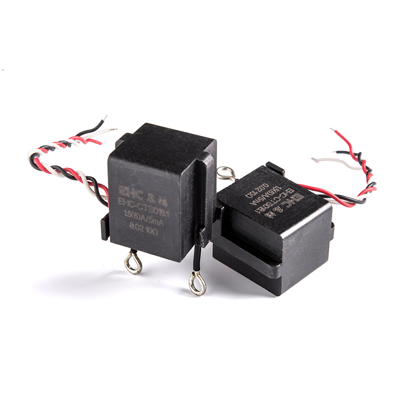
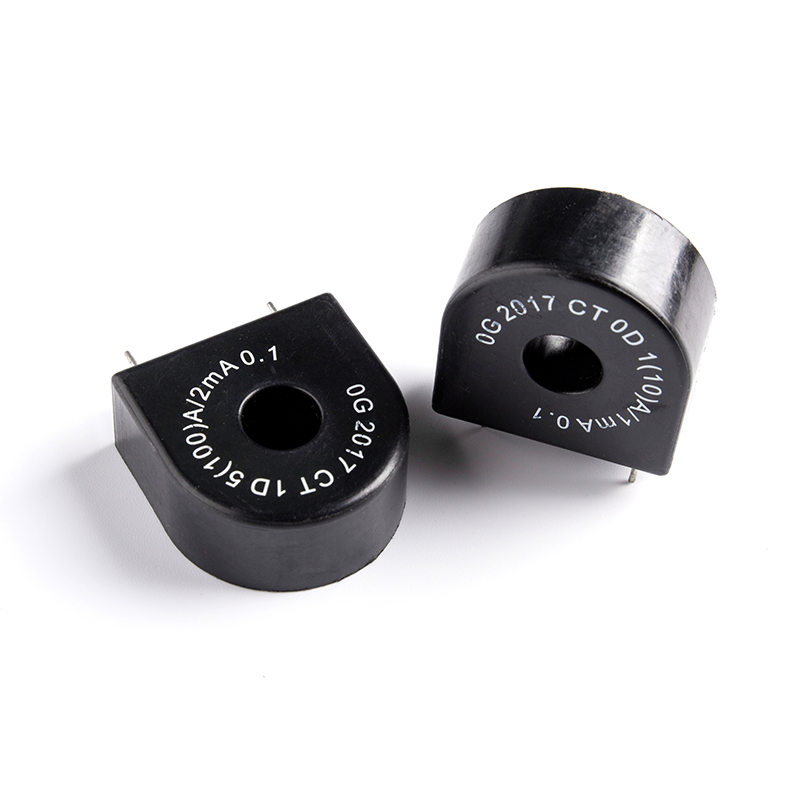
Current Transformers (CT) reduce or step down current levels for metering or protection applications. They are often used with watt-hour meters and protective relays or as trip coils in magnetic circuit breakers.
It is important to select a CT with a turns ratio that is compatible with the measuring instrument or protective relay. In addition, the burden resistor should be carefully selected to minimize noise and signal distortion.
Types
Many different types of current transformers exist for the purpose of measuring the high alternating current levels that are transferred through power systems. Each has its own specific construction and design that allows it to serve different purposes.
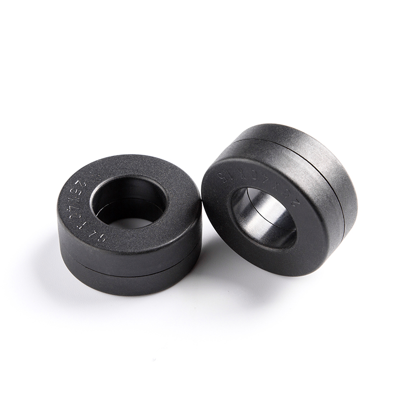
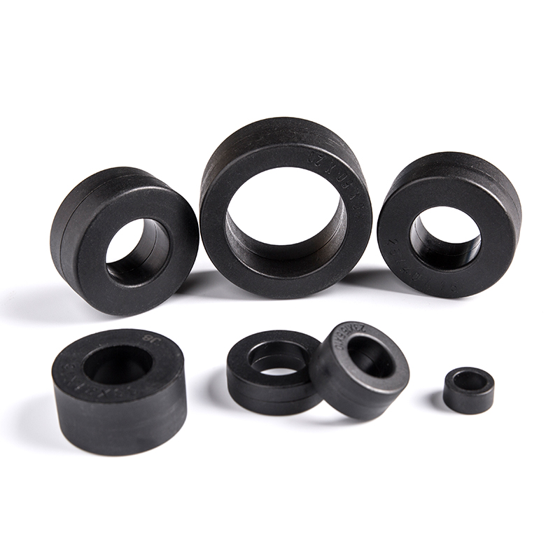
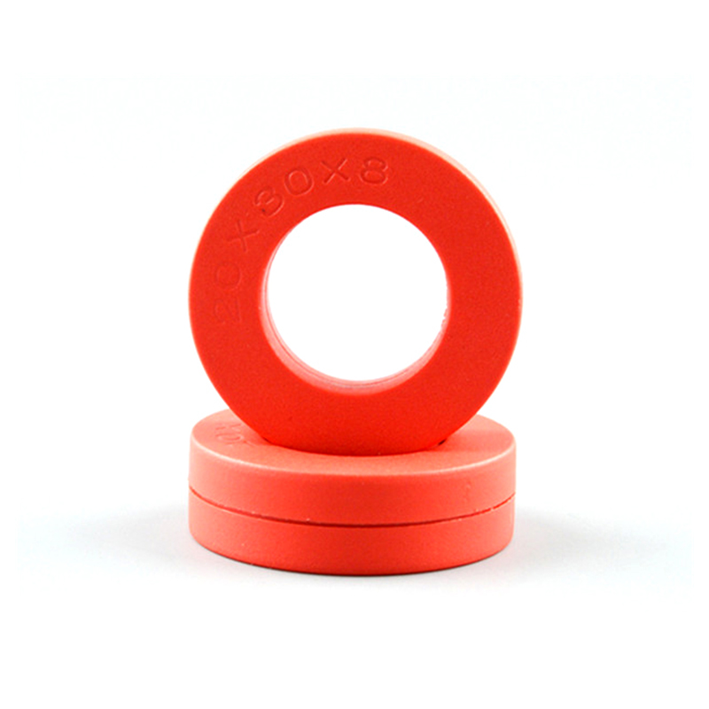
The basic structure of current transformers includes a primary winding, a secondary winding and a magnetic core with insulation material. The type that is chosen must be able to handle the current levels in the system.
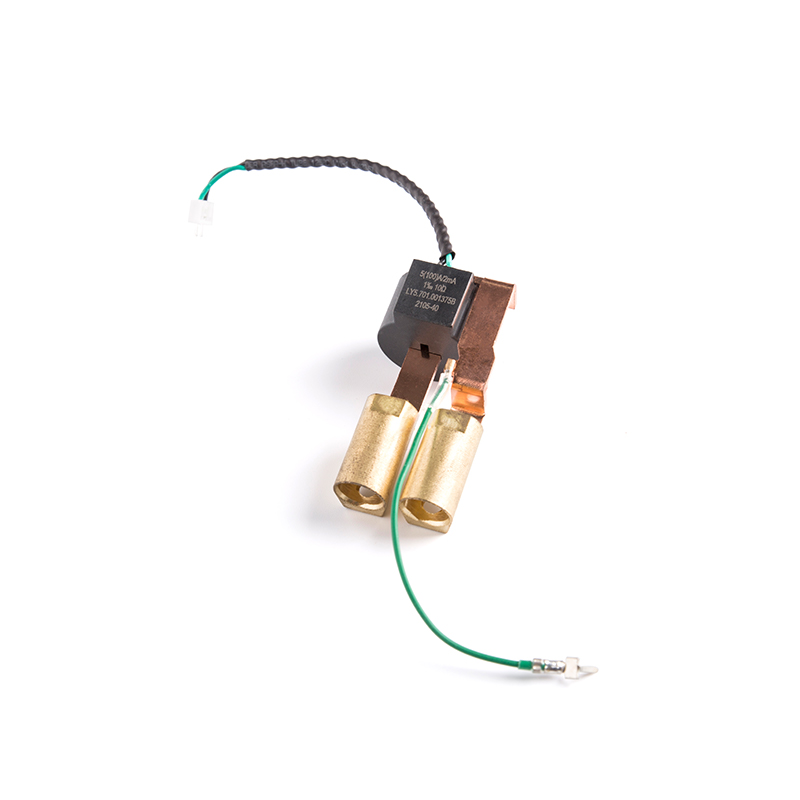
Some types of current transformers use a window-type design that can allow the circuit cable to be slipped over the primary conductor without disconnecting it. The primary conductor in these types may consist of a straight copper bar that passes through the window to provide a single turn or a wound secondary with many turns.
The accuracy of current transformers is rated at full load and is often described by the ratio accuracy class, which is followed by a number that indicates the maximum permissible deviation between the primary and secondary current magnitudes. Some CTs are rated for metering accuracy while others are rated for protection applications.
Applications
Current transformers are used in many metering applications to reduce the high current levels of power electronic circuits to a safe level that can be measured with a metering device. They also provide isolation between the electric circuit's high currents and voltages and the metering or protection circuits.
Generally, the current transformer has a few turns of primary winding and a larger number of turns in the secondary. This arrangement is referred to as a ratio type CT. For example, a primary winding with one turn is configured to produce a secondary current of 5 amps for every 500 amps flowing in the primary conductor.
Other types of current transformers include the window, split core, and bar. The split-core CT allows the primary conductor to be clamped around it and is designed for quick installation. It is also designed to withstand a higher thermal overcurrent and lower failure rate than the bar-type. It is important to note that a current transformer should never be open-circuited while the primary current is running. This will cause the primary magnetic field to saturate and could seriously impair its accuracy.
Turns Ratio
The transformer turns ratio is the relationship between the number of turns on the secondary side and the primary winding. It is an important test to perform when assessing the condition of a current transformer. A transformer turns ratio test is commonly performed during acceptance testing and during maintenance to detect any insulation deterioration, shorted turns or improper connections. It is also used to verify the transformer nameplate rating.
The turns ratio is calculated by dividing the number of primary winding turns by the secondary winding turn count. The result is a factor that is multiplied by the current that passes through the core to create the EMF induced in the secondary winding.
When performing the turns ratio test, the test leads should be connected to the corresponding H1, H2, and H3 transformer terminals/bushings. The H0 test lead can be used if the transformer is wye connected. The measured results should be within 0.5% of the calculated ratios.
Burden Resistor
Many electrical components are susceptible to high currents. Hence, it is important to protect them from damage and ensure they are working properly. Choosing the right current transformer is critical to ensuring that these requirements are met.
One of the most common uses of CTs is for metering and protection applications. They are used in a variety of forms, such as the handheld clamp-on CT and the split core CT. They are also available in various shapes, sizes, and ratings to meet different application needs.
The CT's secondary terminal can be connected to a burden resistor in order to increase the output voltage of the CT. However, it should be noted that the primary current will pass through the burden resistor as well. To determine the proper value for a burden resistor, it is important to consider the CT's turns ratio and its accuracy rating. The higher these values are, the more accurate the CT will be.

 English
 中文简体
中文简体 Deutsch
 日本語
日本語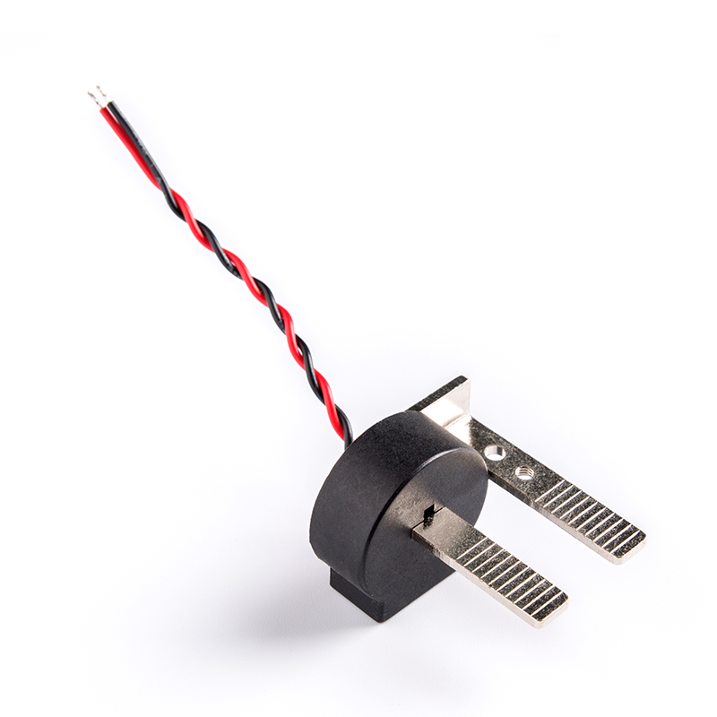
 View More >>
 View More >>
 View More >>
 View More >>
 View More >>
 View More >>
 View More >>
 View More >>