 English
 中文简体
中文简体 Deutsch
 日本語
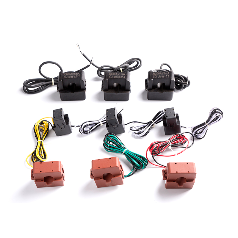
日本語Installing and connecting current transformers (CTs) within an electrical circuit is crucial for accurate current measurement, especially in applications like metering, protection, and monitoring. CTs are used to step down the current flowing through a circuit to a manageable level that can be measured with instruments or devices. Here are the general steps for installing and connecting CTs to ensure accuracy:
Note: Electrical work should only be performed by qualified professionals who are familiar with electrical systems and safety practices.
Safety Precautions:
Before working with electrical systems, ensure that the power to the circuit is safely disconnected. Verify that all equipment is de-energized to prevent electrical shock and hazards.
Select the Right CTs:
Choose the appropriate CTs based on the specific requirements of your application. Consider factors such as the rated current, accuracy class, and burden (the connected load that the CT must drive).
Mounting and Location:
Install the CTs in a suitable location within the electrical circuit. CTs are typically mounted around the conductor whose current you want to measure. The CTs should be securely fixed to prevent movement or vibration.
Wiring and Connection:
Connect the CTs in series with the circuit you want to measure. The primary conductor (the wire carrying the current to be measured) should pass through the central hole or window of the CT. The CT must be oriented properly, with the primary conductor positioned exactly in the center of the hole.
Polarity and Polarity Marks:
CTs are polarity-sensitive. Make sure to observe the polarity markings on the CT. Typically, CTs are marked with a dot or an arrow to indicate the direction of the current flow. Ensure that the direction of current aligns with the arrow or dot.
Burden Connection:
The secondary winding of the CT is connected to measuring devices, such as ammeters or protective relays. The wires from the secondary winding, often color-coded as black and white, should be connected to the appropriate terminals of the measuring device.
Shorting Block:
If the CT secondary circuit is ever opened, it's important to have a shorting block or secondary shorting device. This device safely shunts the secondary terminals together to prevent an open circuit condition. This should be removed when connecting the CT to a measuring device.
Wiring Protection:
Provide proper protection for the CT secondary wiring. Use appropriate conduit or cable management to prevent damage to the wires. Ensure that the secondary wiring is insulated and secure.
Accuracy Check:
After installation and connection, it's essential to verify the accuracy of the CT. Perform a functional test using known currents or with a known load. Ensure that the readings match the expected values.
Seal or Lockout:
Depending on the application and regulatory requirements, you may need to seal or lockout the CT connections to prevent tampering or unauthorized adjustments.
Documentation:
Keep detailed records of the CT installation, including the type, location, and polarity markings. Proper documentation is essential for maintenance and troubleshooting.
Regular Inspection and Maintenance:
Periodically inspect the CTs and connections for signs of wear, damage, or loose connections. Routine maintenance helps ensure continued accuracy.

 View More >>
 View More >>
 View More >>
 View More >>
 View More >>
 View More >>
 View More >>
 View More >>